BBSRC · In-chamber fluorescence for Crossbeam + Katana
In-chamber fluorescence for the Crossbeam and Katana volume-EM stack. The selected optical baseline is now NA 0.55 with Firefli Red. The active 3D model and Blender sensor results now use the NA 0.55 candidate. Live Onshape remains at Rev G.
Updated 18 September 2026 · NA 0.55 model and sensor simulations regenerated · Original Rev G retained as history
Purpose
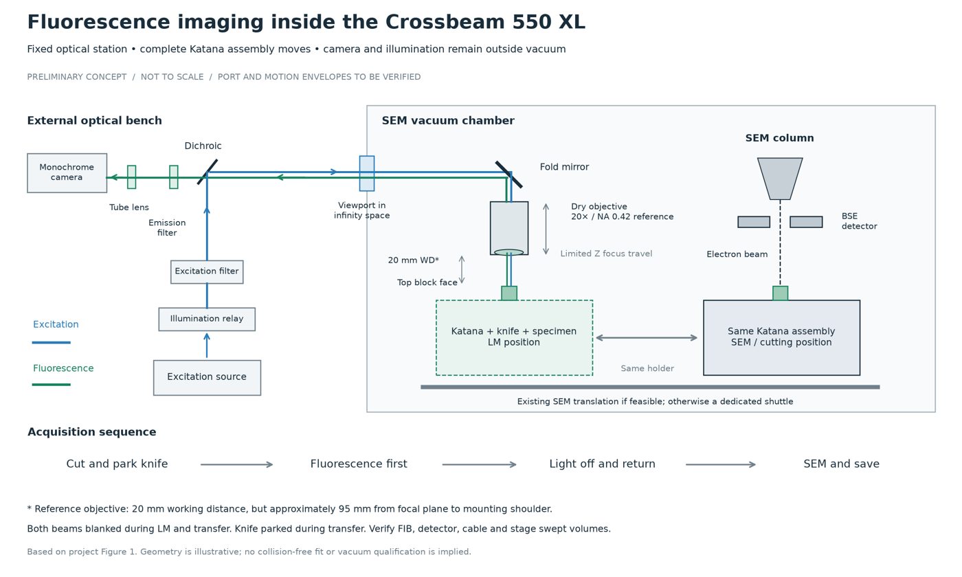
The instrument needs a small fluorescence channel that fits the chamber envelope, uses a long-working-distance objective, and does not collide with the microtome, detectors or stage travel. The design feeds a horizontal camera arm through a dichroic cube and a 45° prism above the objective, with reciprocal LED excitation on the same shared bore.
The active simulation uses the selected NA 0.55 objective with the existing downstream aperture geometry. The updated model is an optical simulation candidate; real optics and whole-assembly chamber clearance still require validation.
Latest baseline — NA 0.55 & Firefli Red
Decision dated 10 September 2026 · Applied to local 3D and Blender simulations 18 September · Live Onshape unchanged
The starting objective is now NA 0.55. The working candidate is the Mitutoyo M Plan Apo 50× with 13 mm working distance and a 4 mm focal length. Its identity and physical envelope must be confirmed before mechanical changes. With the existing ideal 100 mm tube lens, the nominal system magnification is 25×.
| Parameter | Previous Rev G | Updated simulation |
|---|---|---|
| Objective catalogue magnification | 20× | 50× candidate |
| Numerical aperture | 0.42 | 0.55 |
| Working distance | 20 mm | 13 mm |
| System magnification with ideal f100 tube | 10× | 25× |
| Object pixel size | 0.345 µm | 0.138 µm |
| Object field | 662.4 × 414 µm | 264.96 × 165.60 µm |
| Objective-front datum | Z73.58 mm | Z66.58 mm |
The initial sample is Firefli Red-labelled polystyrene, with reported excitation/emission peaks at 542/612 nm. It supersedes the provisional Nile Red channel for initial testing. Fluorescence has been reported after preparation, with high background; quantitative performance is still unverified.
Provisional spectral targets are a green LED around 530–545 nm, excitation around 540/20 nm, a 565–570 nm dichroic transition, and emission around 610/40 nm. These are targets for evaluation, not a purchased or validated filter set. The former 505 nm long-pass dichroic is unsuitable for routing green excitation in this configuration.
The model now includes the 7 mm shift toward the sample, an 82 mm-long conservative objective envelope and the 4.4 mm exit pupil. The recomputed aperture audit passes all 21,654 sampled rays. This does not validate the actual lens, lid or knife clearance, spectral performance or a print release.
New sample-image review
The supplied EVOS image combines red-pseudocoloured RFP fluorescence and transmitted light, acquired with a 20× / NA 0.45 objective. Visible red signal supports testing the selected NA 0.55 objective, but the merged 8-bit RGB image cannot establish fluorescence background, photon SNR or detection limits.
Next measurements need separate original fluorescence and transmitted-light frames, an identically prepared blank, the installed filter-cube identity and particle size. Compare contrast above measured background before choosing the final spectral components.
Historical Rev G geometry and aperture corrections
Earlier layout
Historical mechanicals — Rev G
Rev F vignetted off-axis image and illumination bundles at the shared/image bore, illumination approach and dichroic clear aperture. Rev G enlarges those openings and shifts the tube-lens / camera and LED seats so the sampled pupil rays clear. The 6 September audit records no solid–solid interferences among the 34 assembled parts after the correction; the nine-part print layout regenerated cleanly. These are recorded checks, not a fresh validation of the live CAD.
| Item | Rev F | Rev G |
|---|---|---|
| Shared / image bore | Ø23 mm | Ø40 mm |
| Illumination approach bore | Ø24 mm | Ø40 mm |
| Dichroic clear rectangle | 32 × 22 mm | 46 × 32 mm |
| Dichroic glass envelope | 35.6 × 25.2 × 1.1 | 50.8 × 35.6 × 1.1 |
| Tube-lens / filter envelopes | Ø25–30 mm | Provisional Ø50.8 mm |
| Field stop | Ø1.8 mm | Ø3.6 mm @ f40 conjugate |
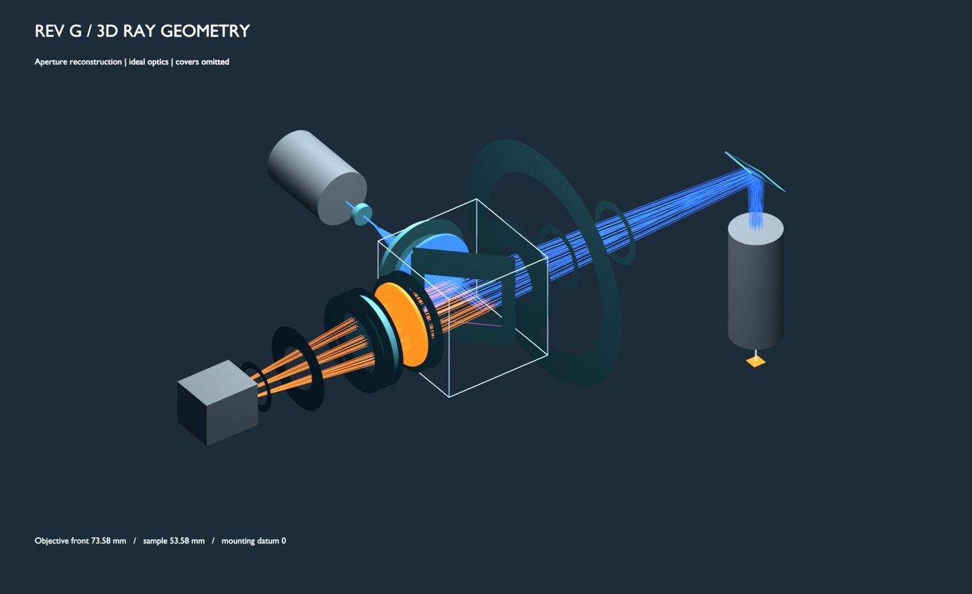
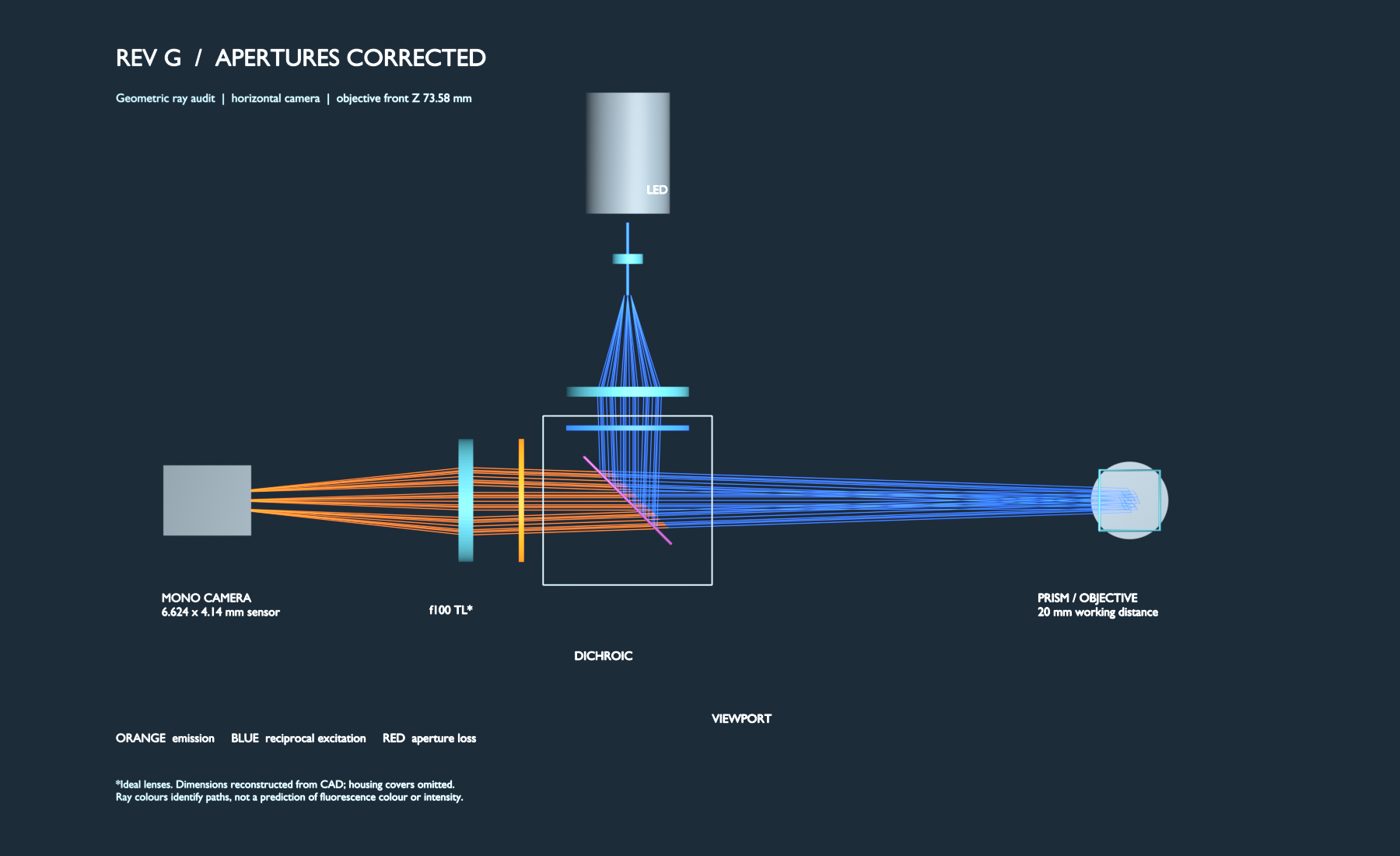
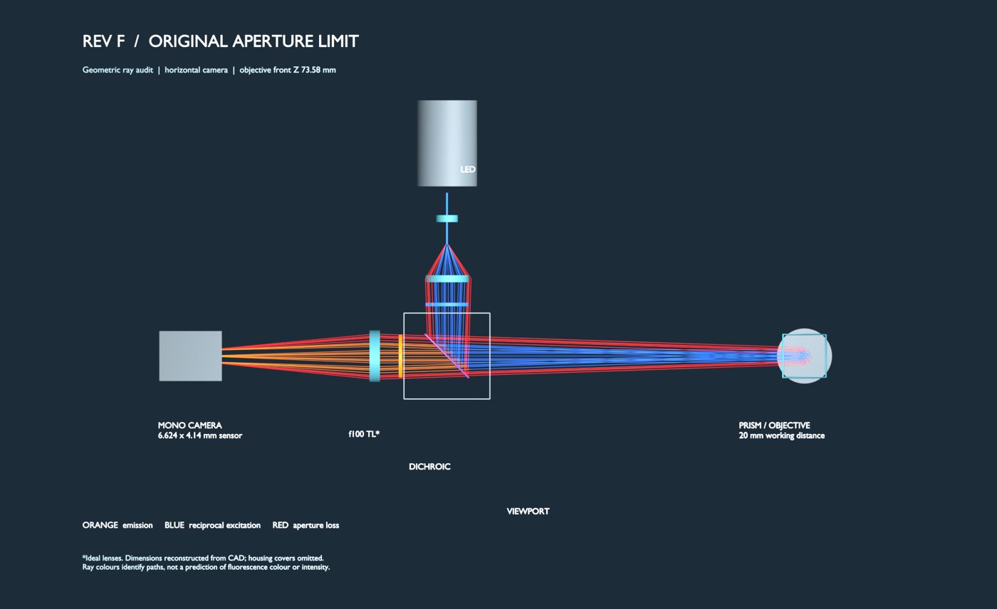
Updated 3D model — NA 0.55 / WD 13 mm
The active model now uses the selected Mitutoyo 50× candidate: NA 0.55, 13 mm working distance and a 4.4 mm exit pupil. The objective is represented by an 82 × Ø34.5 mm conservative envelope, with its front at Z66.58 mm and the shoulder retained at Z148.58 mm. It is not a detailed supplier barrel model or a live Onshape revision.
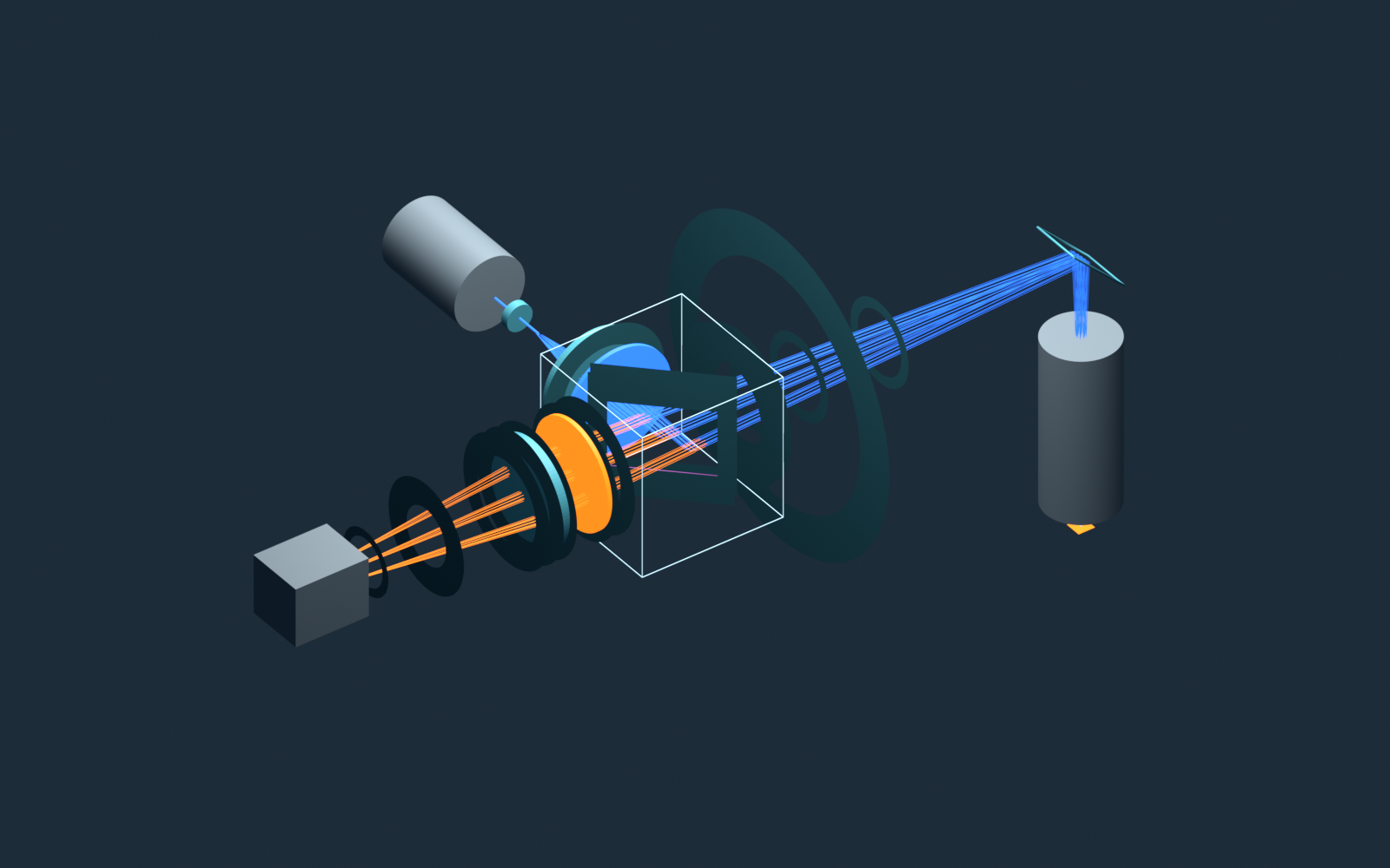
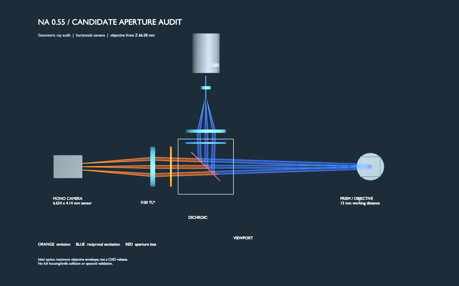
Orange identifies the image branch and blue the reciprocal excitation branch. Colours do not predict fluorescence colour or intensity. Pupil positions and ideal lens transfer remain assumptions.
Model from assets/na055/na055_optical.glb; optional rays in mm. Geometric clearance only.
Blender simulations — updated NA 0.55 sensor view
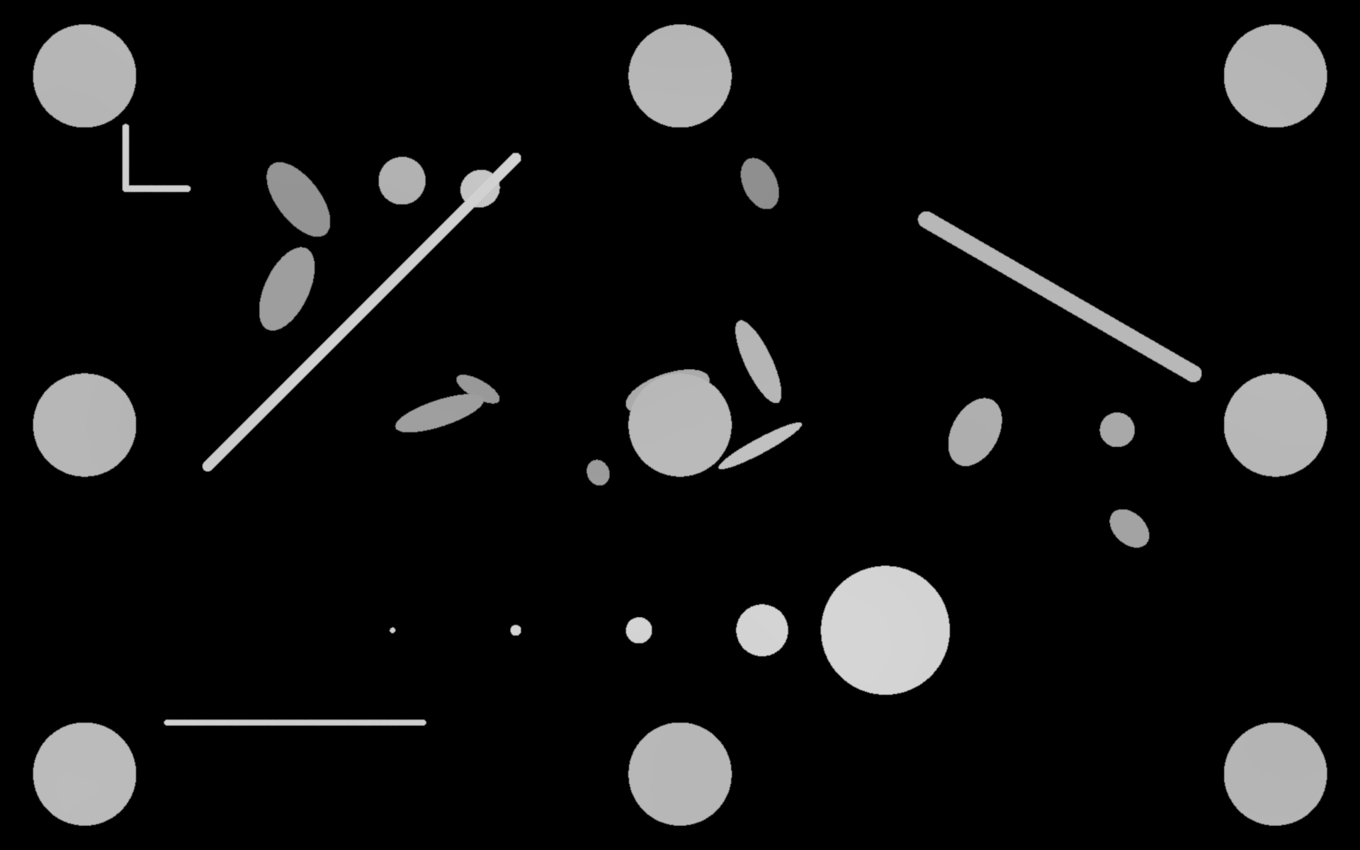
The regenerated Blender scene uses NA 0.55 / f4 / WD13, a 4.4 mm pupil and nominal 25× transfer to the designed sensor. It includes focus, +10 µm defocus, LED-off and uniform-layer controls. The synthetic target was rearranged for the smaller field; this is not a fixed-specimen brightness comparison against Rev G.
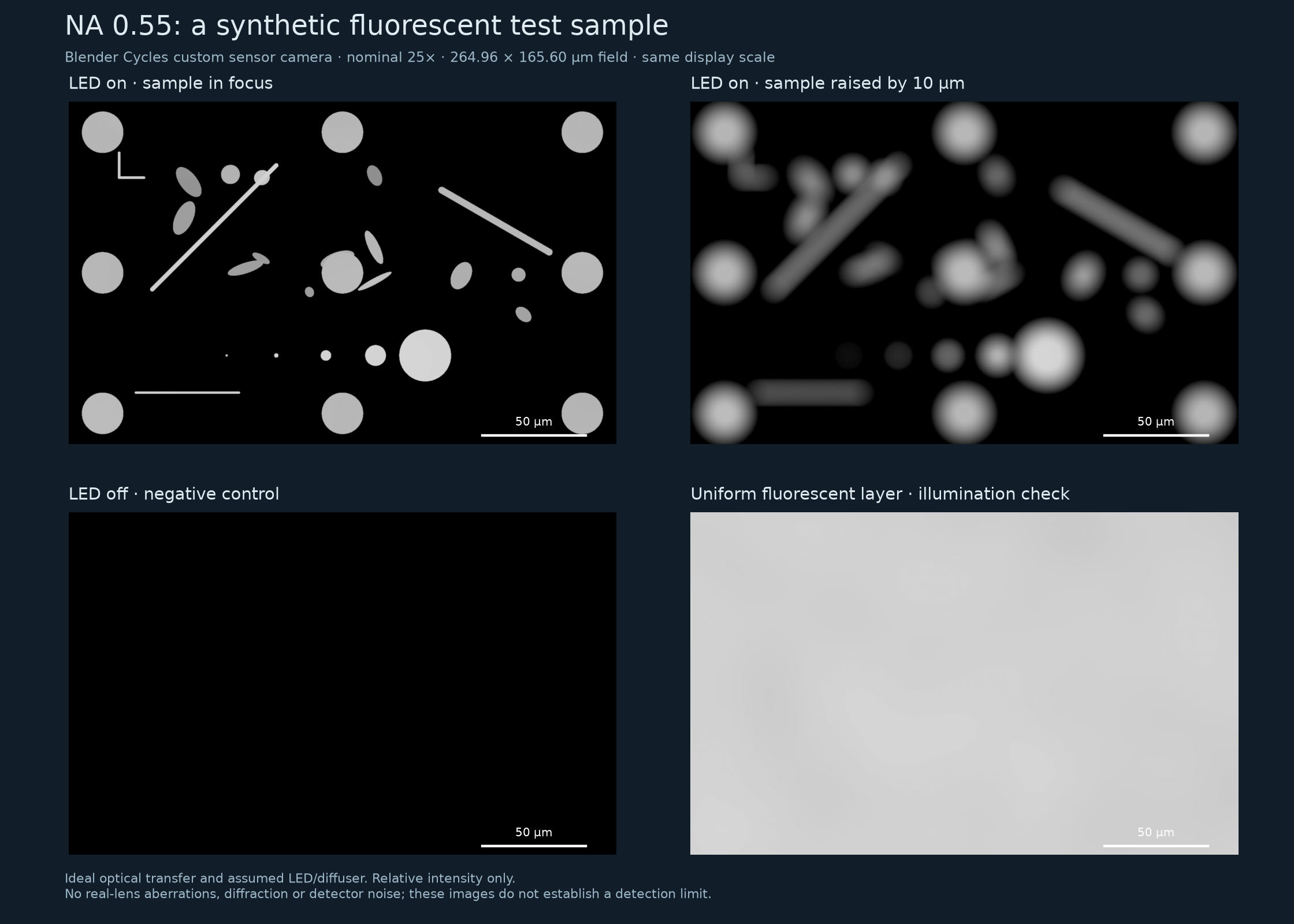
- Focus: a 20 µm reference dot measures 145 pixels (20.01 µm), checking the implemented image scale.
- Defocus: raising the sample 10 µm spreads the signal and reduces the smallest test-dot peak from about 0.6365 to 0.00931 in relative linear units.
- LED off: all pixels are zero in the model’s dark control. Real detector noise is not included.
- Illumination: the assumed LED and diffuser produce a calculated relative irradiance range of 0.913–1.027 across the sample grid, normalised to the centre.
The simulation uses ideal optical transfer and assumed LED/diffuser properties. It does not predict absolute brightness or detection limits, and does not include diffraction, real-lens aberrations, spectral response or camera noise. The new aperture-clearance audit is a separate check; none of these results is a real-lens or whole-assembly validation.



Updated model & simulation downloads
Open the updated sensor scene in Blender 4.5 or later and press F12. LED Power 0 gives the dark control; SAMPLE Location Z +0.010 mm gives +10 µm defocus. Restore Power to 1 and Location Z to 0 for the reference image.
Original CAD and historical files
The links below still refer to Rev G (NA 0.42) and require project access. The live Onshape assembly and print layout have not been changed by this simulation update.
Caveats
This is a geometric clearance result, not a validation of image quality, LED radiance, field uniformity, photon budget, spectral filters, ghosts, MTF, print tolerance, thermal drift or vacuum compatibility. Ø50.8 lens and filter solids are provisional envelopes — not purchased parts. Pupil planes used in the sensitivity sweep are assumptions; Mitutoyo’s proprietary prescription is unavailable. Do not treat ideal thin-lens focus as evidence of real-lens performance. Real tube-lens BFD, relay prescription and SEM/vacuum fit remain open before final print release.